Brushed Motor Driver DRV8871
The DRV8871 driver from Texas Instruments is a small wonder of compactness and simplicity. Like its cousins, it allows to drive a DC motor in PWM (Pulse Width Modulation). It is reversible, with a Deep Sleep and brake mode and all this for motors from 6.5 to 45V with a peak current of 3.6A. Its control voltage is 3.3 or 5V and requires only 3 simple components to operate. It does as well as the L298N driver by being extremely more compact.
For my part they are myTI samples, this circuit is available online at Mouser or AliExpress.
This type of complete module is available at Adafruit, but I find it a little expensive given the components that make it up.
Driver DRV8871
Here are his schematics:
It has 2 logic inputs (IN1, IN2) which drive the H-bridge, consisting of 4 Mosfets of type N. The inputs can be PWM or on/off. A simple 1/4 w resistor allows the max. current to be configured.
In addition, it manages protection in the event of:
- short circuit
- temperature
- current overflow
- under voltage
It is marketed in 8-Pin HSOP format with powerPAD (cooling zone under the circuit).
For my project the current limiting resistance (RILIM) is calculated to give 2.9A max. The formula for calculating it is:
ITRIP(A) = VILIM (kV) / RILIM(kΩ) = 64 (kV) / RILIM(kΩ)
Therefore, depending on the maximum current required, the corresponding resistance can simply be found:
RILIM(kΩ)=64(kV) / ILIM(A)
It is controlled via its 2 logic inputs according to the table below:
| IN1 | IN2 | OUT1 | OUT2 | Desc |
|---|---|---|---|---|
| 0 | 0 | High-Z | High-Z | Roue Libre, Deep Sleep |
| 0 | 1 | 0 | Vmoteur | Avant |
| 1 | 0 | Vmoteur | 0 | Arrière |
| 1 | 1 | 0 | 0 | Frein |
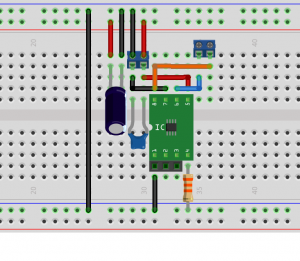
For its real connection:

Fritzing diagrams
Manufacture of printed circuit board
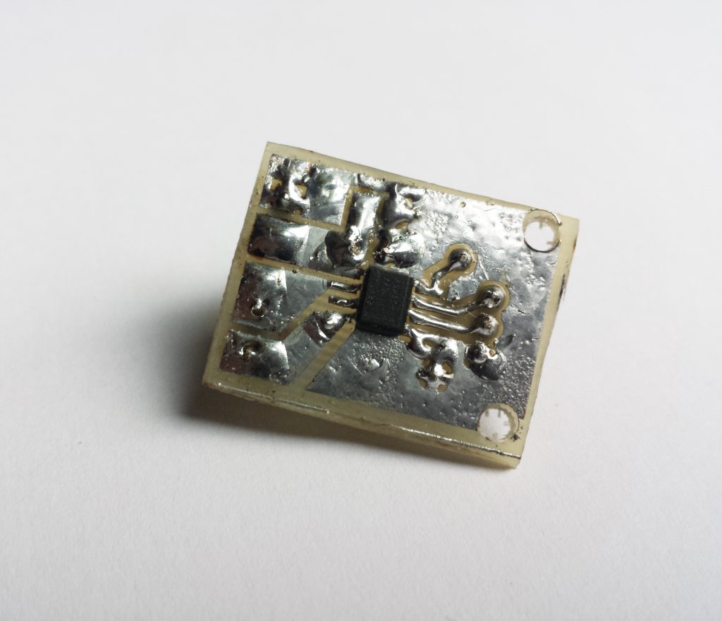
I took advantage of my tuto for the circuit board to create the 2 printed circuits that will accommodate them, my project having to manage 2 12V DC motors. I took inspiration from the reference circuit provided in the Datasheet to draw them. It is a single-sided circuit, although a double-sided circuit is recommended in order to better dissipate heat.

typon 1:1
I put the typon used drv8871_etch_copper_top_mirror.
Mounting
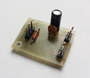
It is therefore necessary per module:
- IC DRV8871
- 22kOhm resistance 1/4w
- tantalum capacitor 0.1uF
- polarized capacitor 22uF 50V
- 2 screw terminals (I replaced them with strips but be careful the spacing of the holes is not the same)
- 1 3-pin male clip
- circuit board
and of course :
- a little soldering
- soldering iron
My video shows the montage. I largely tinned my circuit in order to better conduct current and heat. The IC is mounted on one side of the circuit, the other components on the other.
Conclusion
This small circuit of barely 22mmx28mm easily drives the printer motor under 12v.


What does current limiting actually mean and can I use that to control the speed of the motor?
Current limiting depends on motor characteristics and application. It triggers the IC protection circuit. It cannot be used to control motor speed.