Cybot – episode 0
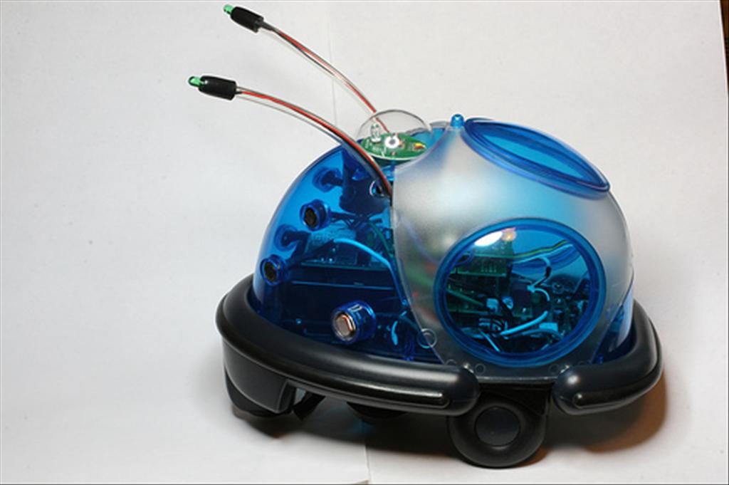
Out of another time, the “Cybot” robot was a major step forward in the democratization of robots in 2003. In the form of a bi-monthly booklet available in bookshops, it was sold as a kit to be assembled. During the months several evolutions have allowed to go so far as to be able to program it via a PC.
My project is to replace its main microcontroller (UC1) with an Arduino Nano, while keeping as many of its modules as possible. I don’t know yet if this will be possible in order to have all the features.
The one I recovered was my nephew’s and quite complete it includes all the parts of Phase I (autonomous robot) and almost all of Phase II (remote control).
A little bit of history:
I will summarize the various elements that are included in the model I have.
- PHASE I (number 1 to 17) :
- Robot main body with power supply card and motors.
- Light tracking thanks to photo resistance.
- Line tracking using an IR transmitter/receiver circuit.
- Obstacle detection with ultrasonic sensors.
- PHASE II (number 18 to 29, 35) :
- IR remote control with display lcd
- IR receiver for the robot with its new microprocessor
There are a total of 4 microcontrollers to control the different modules. They are stacked and each represents a layer with the associated module(s).
If you want to get more information, this Italian site gathers the exhaustiveness of the fascicles, technical information as well as many other robots and subjects, I recommend it: Adrirobot.
The project:
With the elements at my disposal it is not possible to program this robot (this would have been possible with the numbers 36 and 37). In any case, I want to have something accessible for programming and to be able to develop it later. Moreover, I have in a corner of my head the desire to leave it to my children so that they can learn about programming via a Scratch-type interface or directly the Arduino IDE.
The robot is composed of several microcontrollers that are used to control the different elements, they communicate with each other in I2C. A main set of orchestrators for engine control is the one we will change. It should be noted that this robot does not have all its functions activate at the same time, a switch (and via the remote control later) allows to select in which mode you want to use it.
I will move forward step by step by analyzing each microcontroller and module of the Cybot.
Understanding architecture:
The first step is to find all the diagrams or explanations concerning the different modules. The site Adrirobot or lpilsley, less exhaustive but very technical, allows to have almost all the necessary information.
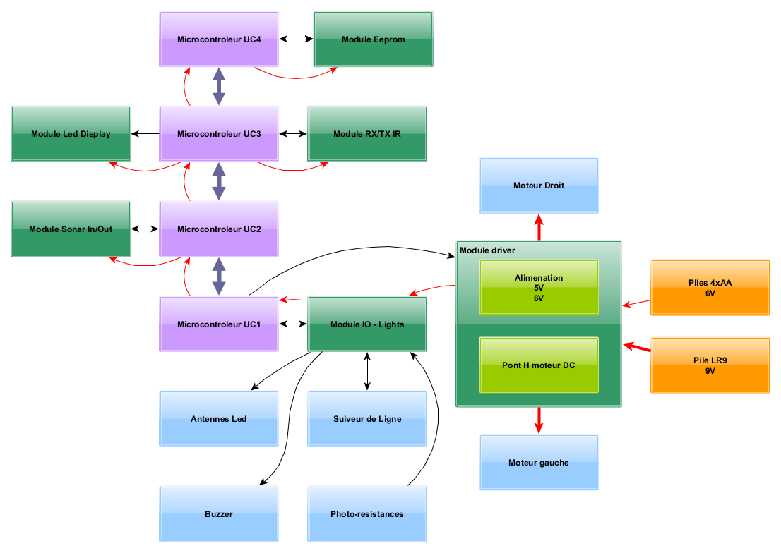
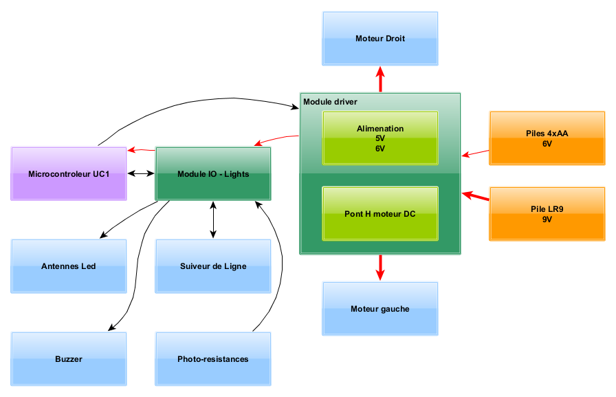
General simplified schematics of Cybot:
The diagrams below show the overall architecture of the robot and the exchanges between its different modules.
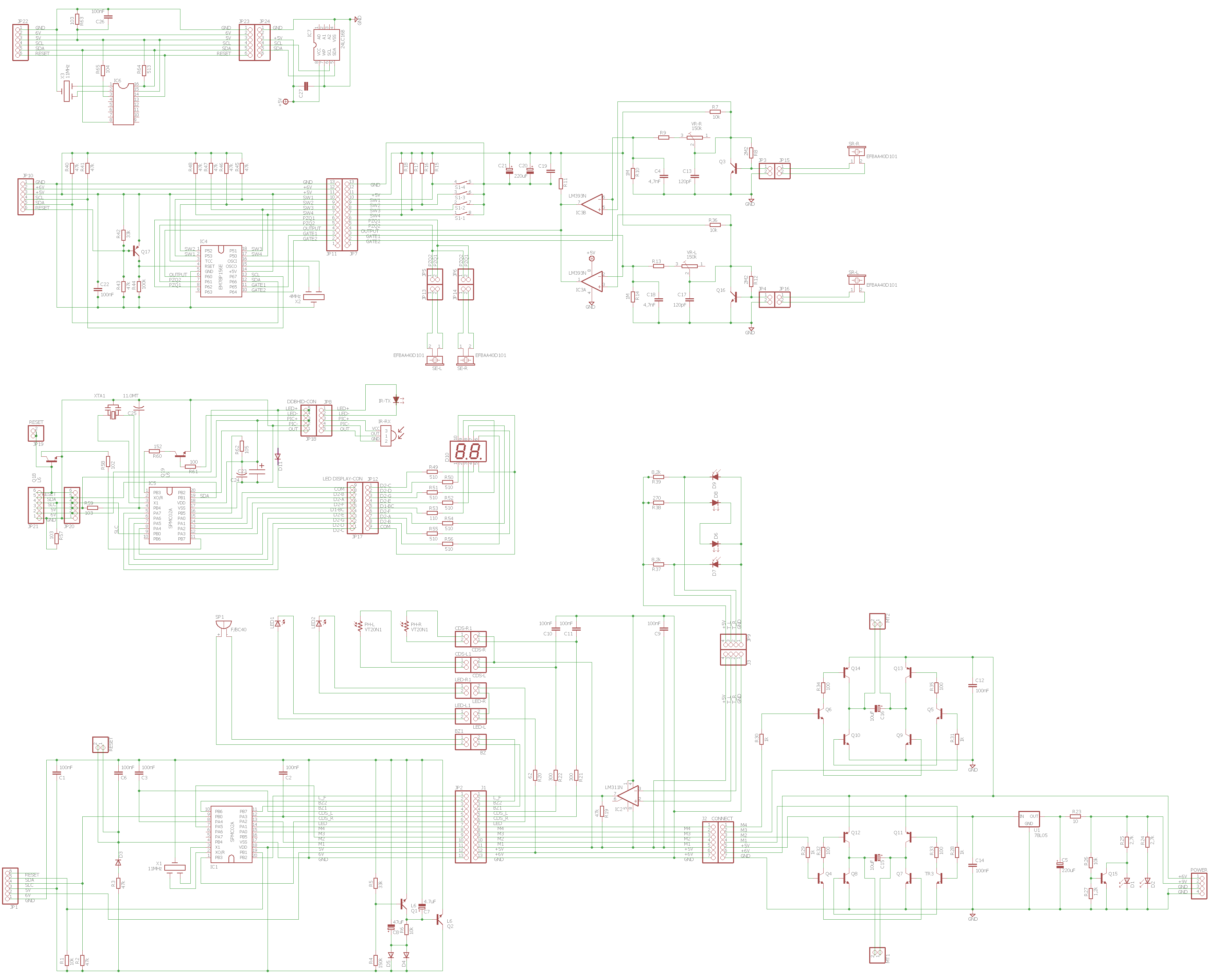
General electronic schematics of Cybot
The Eagle schematics provided by Adrirobot and the reverse engineering of the other modules make it possible to make the complete Eagle schematics represented below in layers as it is mounted in Cybot.
Eagle diagrams and full image:
Individual Eagle diagrams and images :
uc_1_ameliore, uc_2, uc_3, uc_4, display, card_io, card_ir, engine_card,card_sonar, card_tracker_line, eeprom_uc4>
The different material layers:
Layer 1 :
This part manages the main functions of the robot and its power supply.
Motors:
These are R260 DC motors with a maximum consumption of 400mA and a speed of 6500 rpm at 5.5v. The output pinion is a 12 tooth.
They are combined with a reduction gearbox with a wheel/gear gear train 48/12 teeth successively, for a reduction ratio to the wheel of 64:1.
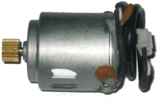
R260 engine
The driver module:
This module has 2 main uses.
The first is the power supply part using the 9V battery to create a stabilized 5V via a 78L05 controller but also 2 LEDs (green and red) indicate the status of the 9V battery.
The second is the motor control part, which is a double H-bridge, powered directly by the 6V of the 4 AA batteries.
These bridges are respectively controlled by inputs M1,M2 and M3,M4 by the microcontroller, which can be in PWM. The voltage applied to the motors, due to the different voltage drops of the diodes, is about 4.5V. Never feed the 2 entrances of the same bridge together at the risk of destroying it.
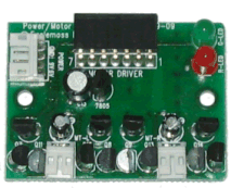
module driver
Motor control panel:
| Moteur | M1 | M2 | M3 | M4 | Fonction |
|---|---|---|---|---|---|
| MT2 Droit | 0 | 0 | arret | ||
| MT2 Droit | 1 | 0 | avant | ||
| MT2 Droit | 0 | 1 | arriere | ||
| MT2 Droit | 1 | 1 | INTERDIT | ||
| MT1 Gauche | 0 | 0 | arret | ||
| MT1 Gauche | 1 | 0 | avant | ||
| MT1 Gauche | 0 | 1 | arriere | ||
| MT1 Gauche | 1 | 1 | INTERDIT |
It allows the 2 motors to be connected via the 2-pin MT1 and MT2 connectors and the 9V and 4×1.5V battery packs.
Power supply connector:
| Pin | Desc. |
|---|---|
| 1 | +6V |
| 2 | +9V |
| 3 | GND |
| 4 | GND |
J1 connector:
| Pin | Desc. |
|---|---|
| 1 | M4 : moteur gauche ar. |
| 2 | M3 : moteur gauche av. |
| 3 | M2 : moteur droit ar. |
| 4 | M1 : moteur droit av. |
| 5 | +5V |
| 6 | +6V |
| 7 | GND |
The IO Lights module:
This module allows you to group together the basic elements of Cybot. It connects to the driver module via the 7-pin connector (J2) on the one hand and to the UC1 module via the 13-pin connector (J1) on the other hand.
-
- The right and left LEDs of the antennas, they are unfortunately not independent, powered by 6V.
- A Buzzer.
- The connection of the line follower is associated with an LM311 comparator.
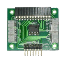
module io lights
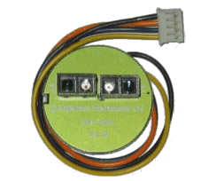
line tracking map
J1 connector:
| Pin | Desc. |
|---|---|
| 1 | M4 : moteur gauche ar. |
| 2 | M3 : moteur gauche av. |
| 3 | M2 : moteur droit ar. |
| 4 | M1 : moteur droit av. |
| 5 | +5V |
| 6 | +6V |
| 7 | GND |
J2 connector:
| Pin | Desc. |
|---|---|
| 1 | L_F : Suiveur Ligne |
| 2 | BZ2 : buzzer |
| 3 | BZ1 : buzzer |
| 4 | CDS_L : photorésistance gauche |
| 5 | CDS_R : photorésistance droite |
| 6 | LED : leds antenne |
| 7 | M4 : moteur gauche ar. |
| 8 | M3 : moteur gauche av. |
| 9 | M2 : moteur droit ar. |
| 10 | M1 : moteur droit av. |
| 11 | +5V |
| 12 | +6V |
| 13 | GND |
The UC1 microcontroller:
This module is based on an 8bit SPMC02 to 6MHz microcontroller.
-
- The 13-pin connector (JP1) manages the different inputs of the IO Lights module.
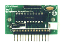
module UC1
JP1 connector:
| Pin | Desc. |
|---|---|
| 1 | L_F : Suiveur Ligne |
| 2 | BZ2 : buzzer |
| 3 | BZ1 : buzzer |
| 4 | CDS_L : photorésistance gauche |
| 5 | CDS_R : photorésistance droite |
| 6 | LED : leds antenne |
| 7 | M4 : moteur gauche ar. |
| 8 | M3 : moteur gauche av. |
| 9 | M2 : moteur droit ar. |
| 10 | M1 : moteur droit av. |
| 11 | +5V |
| 12 | +6V |
| 13 | GND |
JP2 connector:
| Pin | Desc. |
|---|---|
| 1 | RESET |
| 2 | SDA : I2S data |
| 3 | SCL : I2S clock |
| 4 | +5V |
| 5 | +6V |
| 6 | GND |
Layer 2 :
This part manages the robot’s ultrasonic transmitters / receivers, but also its operating mode without the IR TX/RX assembly, i.e. according to which sensor. The selection of the operating mode is made via a 4-contact dipswitch. With the UC3 module it is also used to configure the IR transmission channel.
The sonar module:
The ultrasonic transmitters are directly connected to the UC2 board, so the UC2 board manages the transmitted signal.
Ultrasonic receivers use a differential comparator (LM393) whose outputs are connected to the UC2 board.
The dipswitch allows you to select the Cybot operating modes but also, with UC3, the transmission channel selection. Potentiometers also allow the detection sensitivity to be adjusted.
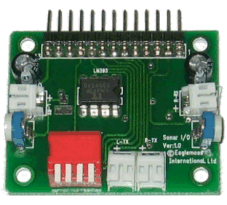
sonar chart
Dipswitch positions:
| Action | SW1 | SW2 | SW3 | SW4 |
|---|---|---|---|---|
| suivis de lumière vitesse rapide | 0 (OFF - haut) | 0 (OFF - haut) | 0 (OFF - haut) | 0 (OFF - haut) |
| suivis de lumière vitesse lente | 1 (ON - bas) | 0 (OFF - haut) | 0 (OFF - haut) | 0 (OFF - haut) |
| évitement vitesse rapide | 0 (OFF - haut) | 1 (ON - bas) | 0 (OFF - haut) | 0 (OFF - haut) |
| évitement vitesse lente | 1 (ON - bas) | 1 (ON - bas) | 0 (OFF - haut) | 0 (OFF - haut) |
| na | 0 (OFF - haut) | 0 (OFF - haut) | 1 (ON - bas) | 0 (OFF - haut) |
| suivis de ligne | 1 (ON - bas) | 0 (OFF - haut) | 1 (ON - bas) | 0 (OFF - haut) |
| suivis d'objet | 0 (OFF - haut) | 1 (ON - bas) | 1 (ON - bas) | 0 (OFF - haut) |
| suivis de ligne | 1 (ON - bas) | 1 (ON - bas) | 1 (ON - bas) | 0 (OFF - haut) |
JP7 connector:
| Pin | Desc. |
|---|---|
| 1 | nc |
| 2 | GATE2 : commande du récepteur droit |
| 3 | GATE1 : commande du récepteur gauche |
| 4 | OUPUT : sortie des recepteurs |
| 5 | PZQ2 : émetteur droit |
| 6 | PZQ1 : émetteur gauche |
| 7 | SW4 : dipswitch 4 |
| 8 | SW3 : dipswitch 3 |
| 9 | SW2 : dipswitch 2 |
| 10 | SW1 : dipswitch 1 |
| 11 | +5V |
| 12 | +6V |
| 13 | GND |
The UC2 microcontroller:
First of all, it manages ultrasonic detectors. It generates a 40kHz signal at 40kHz of 4 positive cycles every 25 ms for the transmitter on the left side (pin 6 of the connector) and 4 negative cycles every 25ms for the transmitter on the right side (pin 5 of the connector). It receives the output signal from the comparator and allows the selection of which receiver to read.
In addition, it also supports the selection of the dipswitch operating mode.
Finally he communicates with UC1 in I2C.
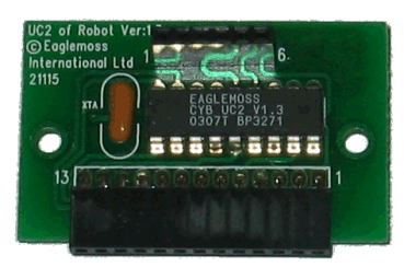
UC2 map
JP11 connector:
| Pin | Desc. |
|---|---|
| 1 | nc |
| 2 | GATE2 : commande du récepteur droit |
| 3 | GATE1 : commande du récepteur gauche |
| 4 | OUPUT : sortie des recepteurs |
| 5 | PZQ2 : émetteur droit |
| 6 | PZQ1 : émetteur gauche |
| 7 | SW4 : dipswitch 4 |
| 8 | SW3 : dipswitch 3 |
| 9 | SW2 : dipswitch 2 |
| 10 | SW1 : dipswitch 1 |
| 11 | +5V |
| 12 | +6V |
| 13 | GND |
JP10 connector:
| Pin | Desc. |
|---|---|
| 1 | RESET |
| 2 | SDA : I2S data |
| 3 | SCL : I2S clock |
| 4 | +5V |
| 5 | +6V |
| 6 | GND |
Layer 3:
This part manages the infrared control part of Cybot. In addition, it also indicates via the LED display the selected infrared channel.
The RX/TX IR module:
In short, it is an infrared transmitter/receiver unit operating at 38kHz.
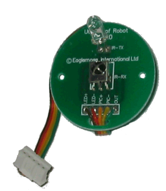
RX/TX card
JP8 connector:
| Pin | Desc. |
|---|---|
| 1 | LED+ |
| 2 | LED- |
| 3 | PIC+ |
| 4 | PIC- |
| 5 | OUT |
The LED Display module:
It is a simple double 7-segment display with its resistors. It indicates the IR transmission channel selected by the dipswitch.
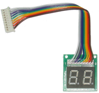
LED display card
JP12 connector:
| Pin | Desc. |
|---|---|
| 1 | D2-C : segment |
| 2 | D2-D : segment |
| 3 | D2-G : segment |
| 4 | D2-E : segment |
| 5 | D1-BC : selection |
| 6 | D2-F : segment |
| 7 | D2-A : segment |
| 8 | D2-B : segment |
| 9 | COM : +6V |
The UC3 microcontroller:
He is in charge of managing the infrared dialogue. This module disconnects the selection of the mode selection that will now be made by the remote control.
It communicates in I2C with the UC1 master module.
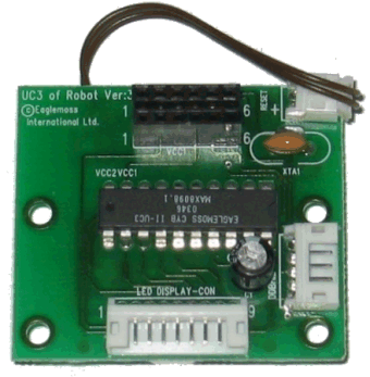
UC3 map
JP17 connector:
| Pin | Desc. |
|---|---|
| 1 | D2-C : segment |
| 2 | D2-D : segment |
| 3 | D2-G : segment |
| 4 | D2-E : segment |
| 5 | D1-BC : selection |
| 6 | D2-F : segment |
| 7 | D2-A : segment |
| 8 | D2-B : segment |
| 9 | COM : +6V |
JP18 connector:
| Pin | Desc. |
|---|---|
| 1 | LED+ |
| 2 | LED- |
| 3 | PIC+ |
| 4 | PIC- |
| 5 | OUT |
JP20/JP21 connector:
| Pin | Desc. |
|---|---|
| 1 | RESET |
| 2 | SDA : I2S data |
| 3 | SCL : I2S clock |
| 4 | +5V |
| 5 | +6V |
| 6 | GND |
Layer 4:
This part will not be detailed because I do not have the elements.
The Eeprom module:
It is an eeprom 24C32 module that communicates in I2C with UC4.
The UC4 microcontroller:
It seems to only handle the dialogue with the eeprom and send the recorded commands to the master module.
Finally:
Here is a complete tour of the robot itself in order to understand what it is made of. I remained as general as possible without going into the precise design of each module. This point will be seen step by step in the rest of the articles. The power of the microcontrollers used probably dictated this choice of feature sharing.
In the following I will study how to connect the arduino in order to replace UC1 and interface the different layers.
